
At a local bar I met up randomly with an old roommate who told me about a project that he was working on. He came into possession of an older spinet piano with an aluminum harp frame. It was really light weight and he had the idea of hanging it on the wall as an art piece with some back lighting and was looking to make it functional as a doorbell.
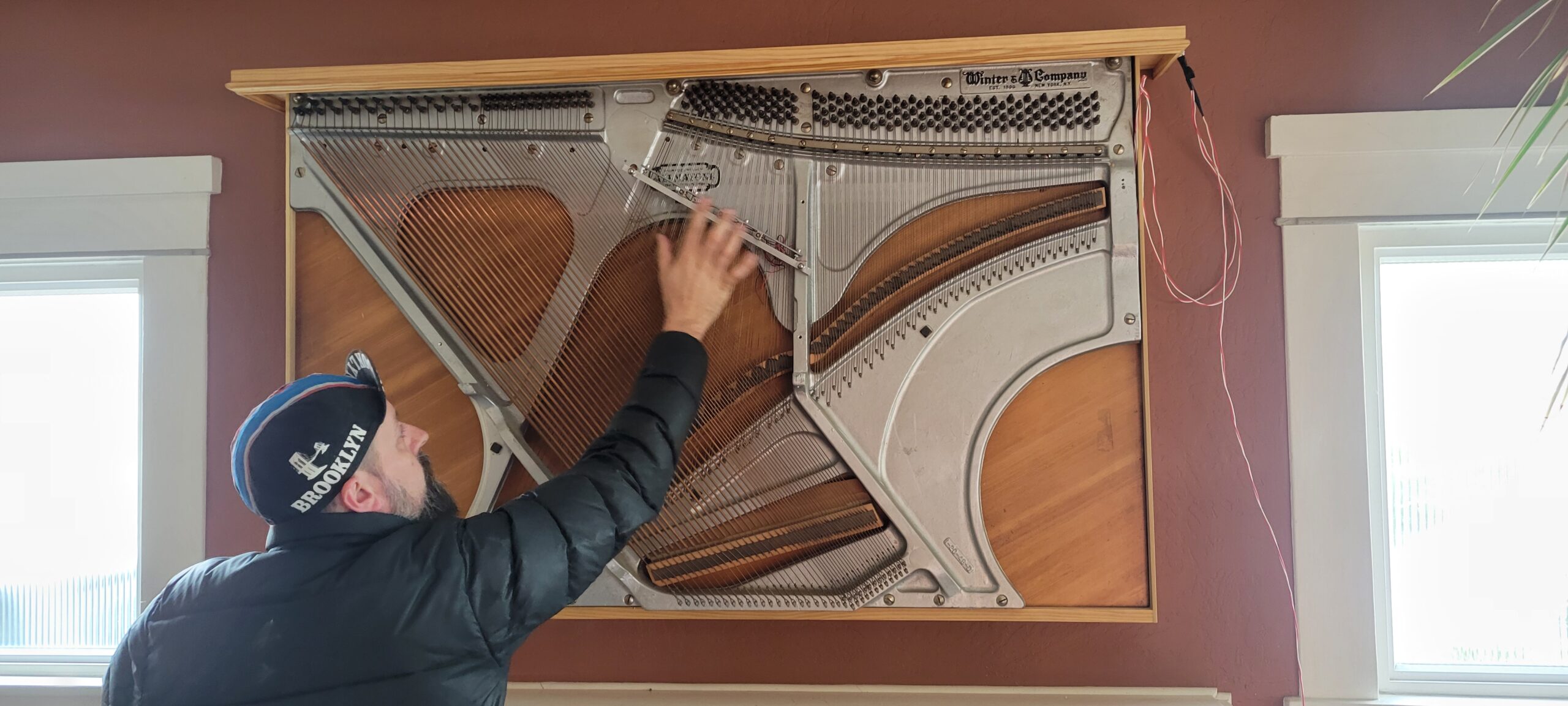
This got me excited and we headed over on our bikes to check it out. It was totally beautiful and really well mounted and framed.
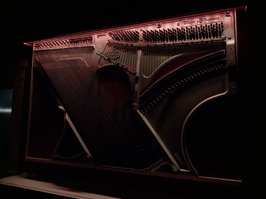
Kev had gone one step further and mounted a rail with solenoids aligned to 4 strings he had tuned to the four notes of the Westminster Chimes (think grandfather clock chimes).
We had a great afternoon catching up and being blown away by how cool this project was, I offered to help out. I had an Arduino Uno that I’d gotten as a birthday gift many years ago and never had a worthy project to use it on. This seemed perfect.
I downloaded the Arduino IDE for Linux as well as SimuIDE to test out code. It was pretty straightforward to make up a project in the IDE, code up the basics for the doorbell, and test in the simulator. You can find the code for this project at KevDoorBell on github.
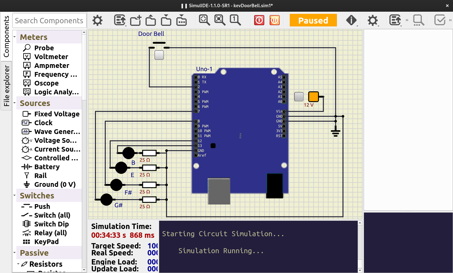
In the simulator I used some simple LEDs to represent each note, G#/F#/E/B. They would flicker on and off with the 10ms note trigger duration. For the actual physical doorbell, this trigger would be actuating a solenoid. To do that, I’d need to look at methods of using the 5v signal off of the Arduino’s output pins to drive the 12v solenoids we had.
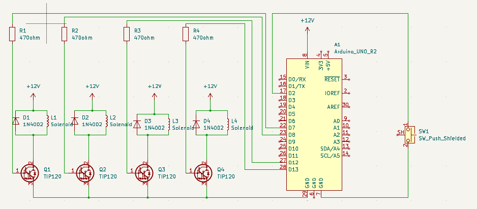
To control the solenoid’s it was easiest to follow the recommendations by MakerGuides to use a Darlington pair transistor to control the flow of 12v. Each solenoid would need a TIP120 transistor, a 1N4002 flyback diode (to eliminate inductive voltage spikes from the coil in the solenoid), and 470Ω resistor to adjust the base voltage in a range that limits the max amperage draw from the Arduino and amperage through the transistor. The components were about $25 through Mouser including a small project box and protoboard for soldering everything together.
I drew everything out in Kicad while we were waiting on parts and it seemed pretty straightforward
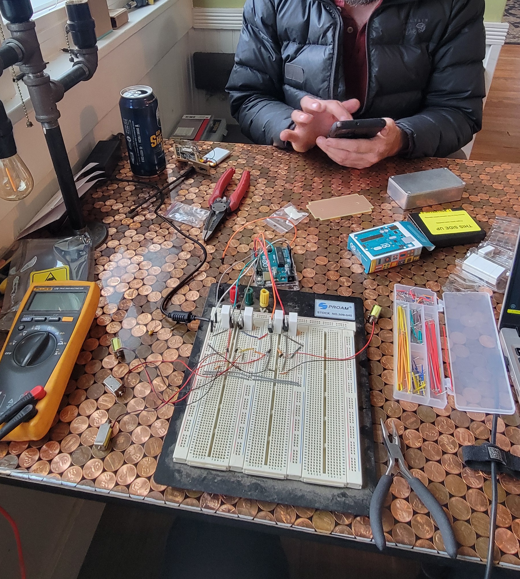
With the ordered parts in hand, we were able to breadboard up the circuit and test with an old 12v power supply. Everything tested fine via multimeter when triggering the doorbell, but I had to head home. Kev soldered up longer wires to the mounted solenoids and was able to get our breadboard setup playing the chimes for the first time.
For the doorbell switch, initially I was using the +5v pin to raise the pin, but with some physical testing we found noise was creating false triggers. I was able to move to using the Arduino internal pullup resistors and swapping the trigger logic to eliminate the problem.
Coming back over on another evening we ate delicious homemade burgers, pulled the breadboard components, made a layout for the protoboard and soldered everything up. I had a tight time window, but we got everything together. This was my first time working on protoboard and it took some real forethought to get the layout right to have a tight footprint and be easy to solder.
The next steps are to wiring up the doorbell part to his door and doing some final testing should be all that’s left to do. Looking forward to wrapping up such a cool project and posting the final results here.
Pingback: Kev’s Doorbell Update | elliottjohnson.net